You have no items in your shopping cart
Oil Sealed Rotary Vane Pumps
- Posted on
- Posted in Vacuum Pump
- 1

How to use rotary vane vacuum pumps and their importance to the overall performance of your vacuum process
Oil sealed rotary vane pumps (aka rotary vane pumps) are the primary pumps on most vacuum systems used in the heat treatment industry. They are also referred to as a “backing” pump when used in combination with a booster pump, or with both a booster and secondary (“high vacuum”) pump, typically a diffusion style. A rotary vane pump can also be used alone when high vacuum is not required and slower pump-down is acceptable.
Two-stage designs are available, which utilize two rotors in series internal to the pump. Single-stage designs can provide a vacuum of 3 x 10⁻² Torr (4 x 10⁻² mbar), while two-stage designs can achieve 3 x 10⁻³ Torr (4 x 10⁻³ mbar).
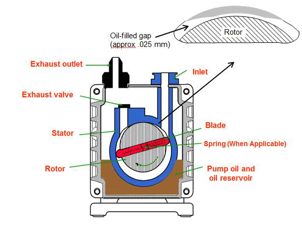
Figure 1 | Cross-sectional view of a rotary vane pump3 (Figure courtesy of Nigel S. Harris M. Sc, C. Phys., author “Modern Vacuum Practice“, 3rd Revised Edition, Kurt J. Lesker Company, 2007)
Due to the prevalence of rotary vane pumps, it is important for designers and users of industrial vacuum equipment to have a good understanding of how these pumps function. This series of articles will cover pump principles of operation, pump designs, pump oils, single-stage versus two-stage pump designs, contamination and gas ballast (manual and automatic), common accessories, applications, troubleshooting and pump maintenance.
Principles of Operation
Of the various vacuum pump technologies, rotary vane pumps are considered wet, positive displacement pumps. They are often called “wet” pumps because the gas being pumped is exposed to oil used as a lubricant to help provide the seal.
For this reason, the oil is carefully selected and specially designed for the application. Positive displacement indicates that the pump works by mechanically trapping a volume of gas and moving it through the pump, creating a low pressure on the inlet side.
Pump Design
Rotary vane pumps (Fig. 1) are designed so that the stator of the pump is immersed in oil and contains a rotor which is eccentrically mounted. The rotor contains two vanes which slide in diametrically opposed slots. The vanes can be spring loaded, but otherwise, rely on centrifugal force to push outward against the stator wall. As the rotor turns, the tips of the blades are in contact with the stator wall at all times.
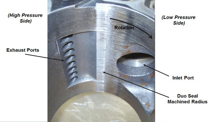
Figure 2 | Internal view of the upper portion of a rotary vane pump (courtesy of Edwards Vacuum)
The entire assembly (Fig. 2) is machined and assembled with tight tolerances so that the gap between the top of the rotor and the stator wall (often referred to as the “Dou seal”) is approximately .025 mm (1.0 mils). This seal is filled with oil, providing a seal between the inlet and outlet sides. The oil is circulated from the oil reservoir into the pump interior and is exhausted through the exhaust valve with the pumped gas.
The ultimate pressure achievable by the pump is limited by back-leakage through the Duo seal and by the outgassing of the lubricating oil. The outlet pressure can be as high as 1000 mbar (750 Torr) and the inlet as low as .01 mbar (0.0075 Torr), which means the pressure differential across the oil-filled seal is roughly 100,000:1 (1000:0.01). At pressure differentials greater than this, back-leakage across the seal will occur, which represents one of the limiting factors in the ultimate vacuum achieved by rotary vane pumps.
There are four stages of operation in a typical rotary vane pump (Fig. 3)
- Induction. The first 180° rotation of the rotor induces the gas into the pumping chamber. The volume occupied by the gas increases due to the crescent-shaped space created by the offset-mounted rotor. The gas pressure decreases in proportion to the increase in its volume (Boyle’s law). This draws the gas into the pump and generates the required vacuum.
- Isolation. The uppermost vane passes the inlet port, sealing it off from the gas being pumped.
- Compression. Further rotation compresses and heats the gas ahead of the lowermost vane, reducing its volume due to the decreasing space between the rotor and stator.
- Exhaust. As the lowermost vane continues its rotation, the pressure in front of it increases sufficiently to force the exhaust valve open, discharging the gas at a pressure slightly above atmospheric.
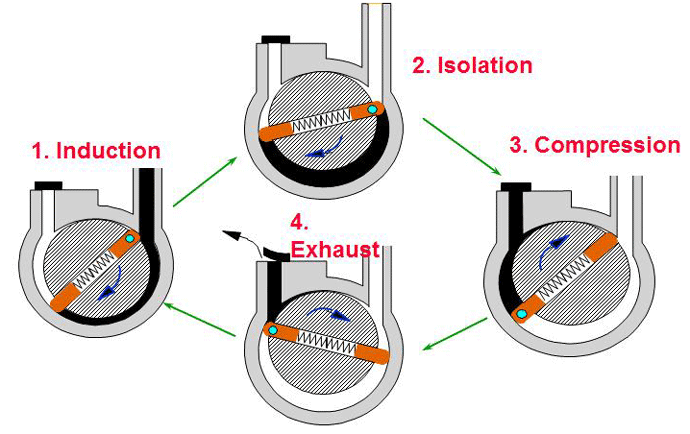
Figure 3 | Four stages of a rotary vane pump (courtesy of Edwards Vacuum)
One of the critical components in a rotary vane pump is the exhaust valve (Fig. 4), which is fed by multiple ports. One common valve design uses an elastomer (artificial rubber) or fluoro-elastomer, with a metal backing plate. The metal backing plate limits the movement of the elastomer part of the valve. Some valves are all metal with no elastomer but this design is susceptible to an effect known as “suck-back” if the pump stops under vacuum. Since the valve does not use elastomer, oil can leak past it and be “sucked” back through the pump and into the vacuum chamber or furnace. Since the valve opens and closes with every rotation it is a source of noise and is susceptible to wear, whether elastomer is used or not. With a pump rotational speed of 1750 RPM, for example, the valve will open and close 2.5 million times every 24 hours at a frequency of 29 Hz. The valve operates mechanically and is forced open by the pressure created by the pump, then closed by atmospheric pressure.
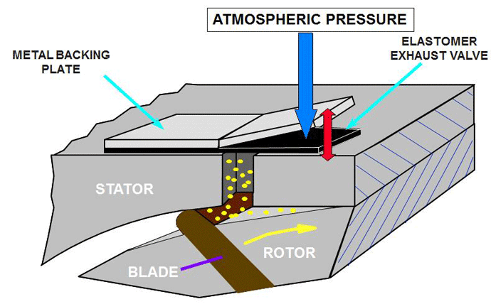
Figure 4 | Exhaust valve on a rotary vane pump3 ((Figure courtesy of Nigel S. Harris M. Sc, C. Phys., author “Modern Vacuum Practice“, 3rd Revised Edition, Kurt J. Lesker Company, 2007)
Rotary pumps are lubricated with oil, which not only provides a seal between the high and low-pressure sides of the pump but also lubricates the pump bearings and other rotating components. Some pump designs, especially older ones using circulation of the lubricating oil relied on a vacuum feed system whereby the vacuum generated by the pump itself was also employed to draw the lubricating oil through the rotor bearings. Other pumps use spring loaded lip type shaft seals around the rotor shaft. This is a dynamic style seal, which also requires lubrication.
Although vacuum feed oil distribution is still used, more modern pumps use a separate oil pump, to circulate the oil via passages machined into the stator to the rotor bearings and seals (Fig. 5). When the vacuum pump is operating, its rotation also rotates the oil pump, which is mounted to the same shaft and develops a positive oil feed pressure of 0.4 bar (300 Torr) above atmospheric pressure. This pressure lifts a spring-loaded elastomer disc which allows oil to flow into a trough feeding the pump interior and rotor bearings as well as the vanes of the vacuum pump. When the vacuum pump stops, the oil pump pressure is no longer present to force the elastomer disc open, and therefore it closes, preventing the suck back of oil through the pump and into the vacuum chamber. Whether or not an oil pump is used, the excess oil is exhausted from the pumping mechanism via the exhaust valve.
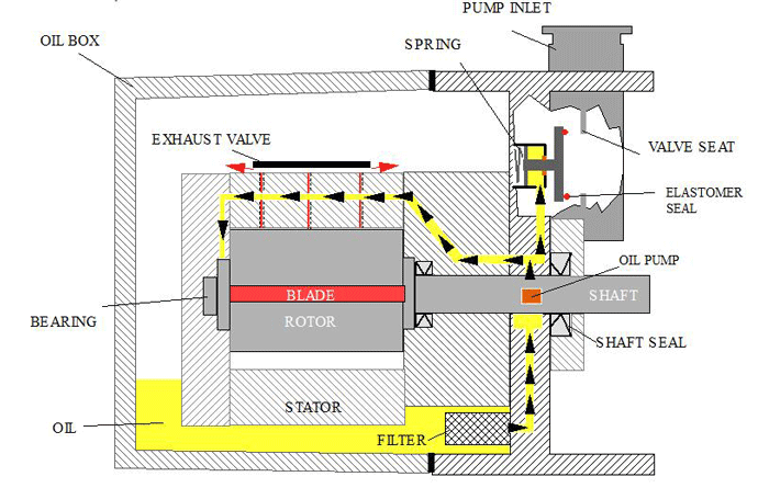
Figure 5 | Oil pump and distribution system (courtesy of Edwards Vacuum)
On vacuum pumps that use a separate oil pump, a hydraulically operated inlet isolation valve can also be incorporated (Fig. 6). In this design, some of the circulated oil is directed to a piston, which is connected to an inlet valve located where the gas enters the pump from the vacuum chamber. The piston uses the hydraulic pressure generated by the oil pump to open the inlet valve, permitting the gas to enter the pump from the chamber. The valve is spring loaded and uses an elastomer seal to stop the flow of gas within 0.5 seconds of pump stoppage. This provides additional protection against suck back into the vacuum chamber.
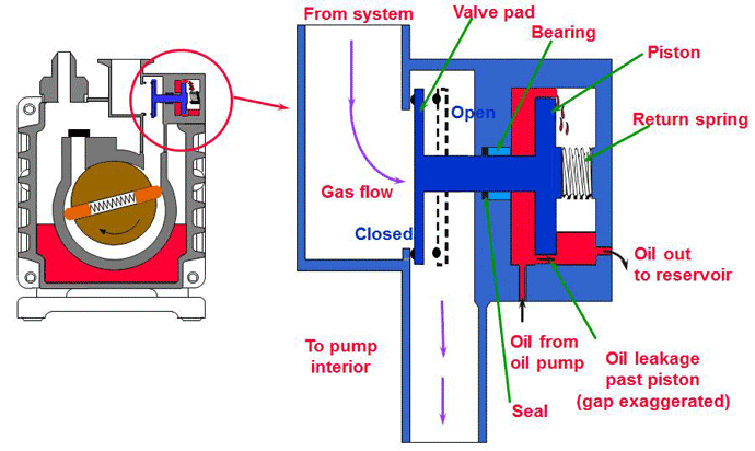
Figure 6 | Hydraulically operated inlet isolation valve (courtesy of Edwards Vacuum)
Types of Oil
The oil used in rotary vane pumps is carefully selected. In addition to providing lubrication of the rotor bearings, it must:
- Provide a seal between the vanes and the rotor.
- Generate the Duo seal between the tips of the vanes and the stator.
- Provide cooling of the stator by transferring heat to the outer casing.
- Offer corrosion protection of the metal parts from the gas being pumped.
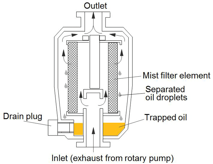
Figure 7 | Oil mist filter3 (Figure courtesy of Nigel S. Harris M. Sc, C. Phys., author “Modern Vacuum Practice“, 3rd Revised Edition, Kurt J. Lesker Company, 2007)
In addition, the vapor pressure of the oil is critical because the oil is exposed to the gas being pumped from the chamber. If the oil pressure is too high, it will vaporize when exposed to vacuum, allowing oil vapor to contaminate the vacuum chamber (referred to as backstreaming). The oil vapor pressure is generally one of the factors limiting the ultimate achievable. For the reasons above, careful consideration must be given to the selection of the oil. Typical motor oil, for example, is not sufficiently refined for use in a vacuum pump, has insufficient resistance to chemical attack, and contains additives that may be detrimental to the process being performed in the vacuum chamber. In addition, the viscosity must be considered. Lower viscosity oils are used for lower operating temperatures, and smaller pumps, while medium viscosity oils are used for medium to large pumps.
Oils designed specifically for rotary pumps are distilled mineral oils to which hydrogen atoms have been attached to any loose molecules in the chain. This process, referred to as hydrotreating, provides a strong, stable formulation with low vapor pressure. For applications where the vacuum pump may be exposed to reactive or corrosive gases carried in the pumped gas, specially engineered oil is used which has been further processed to remove impurities. Where a high concentration of oxygen or other chemically reactive gases are present, highly inert, man-made lubricants are recommended. This perfluoropolyether (PFPE) fluid has good temperature resistance but must not be exposed to temperatures above 280°C (535ºF) at which point it releases toxic vapors. PFPE fluids are available under the trades names (e.g., Fomblin (Solvay Solexis) and Dupont’s Krytox). If the incorrect oil is used in a chemically aggressive environment, it will break down and leave a tar-like residue, which will block the internal passageways and cause pump overheating and failure resulting from insufficient lubrication.
Due to the inherent design of the rotary pump as a “wet” pump, some oil is expelled out of the pump as a mist, along with the gas being transferred. For this reason, an oil mist filter (Fig. 7) is employed to capture the expelled oil. After leaving the pump, the pumped gas is passed through the mist filter, which contains a filter element that reduces the oil mist into droplets and collects it. The captured oil can be drained manually, or through other accessories returned to the pump in a closed loop. It can return either by gravity to the oil box or by suction through the gas ballast (to be discussed later). The filter element is a consumable product and must be periodically replaced.
In the article above, we elaborated on the principles of operation of oil sealed rotary vane pumps including basic pump design, and pump oil. In the following section we continue that discussion focusing on operational features and the inner workings of these pumps.
Single Stage vs Two Stage Pumps
One of the limiting factors of a rotary vane pump is the Duo Seal, which is the oil filled non-contact seal in the small 0.025 mm (0.001”) space between the rotor and the stator at the top of the pump. In a single stage rotary vane pump, the pressure difference across the seal can approach 100,000:1 (1000 mbar vs. .01 mbar). Above this, the duo seal will start to leak oil from the high-pressure side to the low-pressure side (Fig. 8). This creates backstreaming, that is, the movement of pumping oil back into the vacuum furnace chamber.
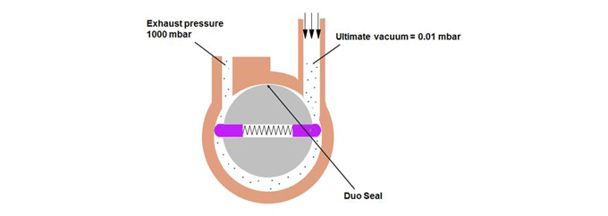
Figure 8 | Rotary vane pump Duo Seal (courtesy of Edwards Vacuum)
In order to generate a higher vacuum using a rotary vane pump, a two-stage pump design is used. The two-stage pump utilizes two rotary vane pumps in series (Fig. 9). The outlet of the high-vacuum stage is piped to the inlet of the low-vacuum stage. Since the inlet to the low-vacuum stage is considerably lower than atmospheric pressure, this design results in lower pressure at the outlet of the high-vacuum stage, as opposed to the single-stage design, which experiences atmospheric pressure at the outlet. This reduces the pressure differential across the Duo Seal and the vanes in the high-vacuum stage, allowing it to operate at a higher inlet pressure. The two-stage rotary vane pump can achieve an inlet pressure of 3 x 10⁻³ Torr (4 x 10⁻³ mbar). There is no exhaust valve located between the high-vacuum and low-vacuum stages, but there is one at the outlet of the low-vacuum stage
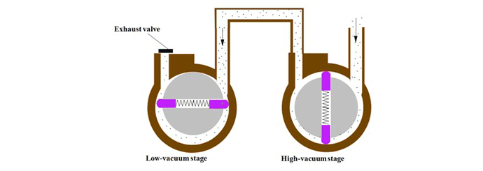
Figure 9 | Two-stage rotary vane pump concept (courtesy of Edwards Vacuum)
Mode Selection
Some two-stage rotary vane pumps are provided with the ability to operate in either high-throughput mode or high-vacuum mode. The mode is selected by turning a knob located on the pump control panel. The mode selector controls the flow of pressurized oil to the high vacuum stage of the pump, which changes the characteristics of the pump. In the high-throughput mode, the oil pressure (and therefore flow) is increased, and in high-vacuum mode, the oil flow is decreased. This feature overcomes the problem at higher pressures of an insufficient pressure differential across the low-vacuum stage thus ensuring an adequate supply of oil into the high-vacuum stage (which is later in the lubrication circuit). When running at higher vacuum, this issue does not occur. The pressure difference is sufficient to provide adequate lubrication in the high-vacuum stage.
The high-throughput mode is used to provide faster drawdown at inlet pressures greater than approximately 38 Torr (50 mbar). A typical cycle might start out in the high-throughput mode to evacuate the vacuum chamber as quickly as possible, then be switched into high-vacuum mode at 38 Torr (50 mbar) to achieve ultimate vacuum. The high-throughput mode is also used to pump condensable (dirty) vapor, and to decontaminate the pump oil when necessary. High-vacuum mode can only be used when the pumped gases are clean.
With the combination of mode selection and gas-ballast (see below) the pump performance can be optimized. A wide range of pumping characteristics (i.e., pressure versus flow performance) is achievable through the selection of these two modes in combination with (high, low, or no) gas ballasting (Table 1). The mode selector switch can be actuated while the pump is on or off, and some larger pumps switch between modes automatically.
Isolation (Anti-Suckback) Valve
Rotary vane pumps are often equipped with an inlet isolation valve (aka anti-suckback or vacuum safety valve). As the name implies, this device closes when pumping stops, preventing gas (or air) from being sucked back into the vacuum chamber through the pump. When pumping is stopped and the valve closes, air enters the pump outlet, equalizing the pressure inside the pump with that outside the pump outlet. This prevents oil in the casing from filling the stator chambers. When the pump is turned back on, the valve does not open immediately but is delayed until the pressure in the pump has reached the approximate pressure in the vacuum chamber, thereby also preventing suckback while the pump is reaching pressure. This isolation valve (c.f., Oil Sealed Rotary Vane Pumps Part 1) is hydraulically actuated. In two-stage rotary vane pumps, the isolation valve is located on the high-vacuum stage.
Gas Ballast
Moisture and vaporized contaminants (typically from dirty work introduced into the vacuum chamber) will find their way into the pump oil and interfere with efficient pump operation. As a result, it becomes difficult to reach ultimate vacuum and takes longer and longer times to do so as the oil loses its ability to provide a seal between the vanes and stator, and at the Duo Seal, resulting in reduced pumping efficiency. Also, the properties of the oil change, causing insufficient lubrication and introduce the possibility of internal corrosion. To avoid these problems, a simple yet highly effective gas ballast (aka gas ballasting) operation is used.
Gas ballasting is the injection of a non-condensable gas (e.g., nitrogen or air) into a rotary vane pump during the compression stage resulting in reduced condensation. The ballast gas is injected through a one-way (aka “gas ballast”) valve, located at the top of the pump (Fig. 10). One way to think of the use of a gas ballast is that opening the gas ballast valve deliberately destroys the efficiency of the pump, which in turn causes the pump oil to heat up and drive moisture and other volatile vapors out of the oil where they can be sent up the vent stack.
The theory behind this is that the injected gas dilutes the vapor in the pumped gas so that the partial pressure of the vapor never reaches saturation during compression. Injection starts at the beginning of the compression cycle. After it starts, the pump rotor continues to rotate, increasing the pressure generated in the pump, which forces the one-way ballast valve closed, but not until sufficient dilution has occurred. As the rotor continues to turn, the pump discharge valve is forced open and discharges the mixture of pumped gas, ballast gas, and vapor.
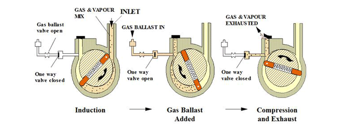
Figure 10 | Principle of gas ballasting3 (Figure courtesy of Nigel S. Harris M. Sc, C. Phys., author “Modern Vacuum Practice“, 3rd Revised Edition, Kurt J. Lesker Company, 2007)
In addition to diluting the condensable vapors, the gas ballast raises the temperature of the process gas 10-20°C (18 – 36°F), which further inhibits condensation. In addition, used during normal operation to prevent vapor condensation, gas ballast is also used to decontaminate pump oil that has already been contaminated with condensed vapor. This can take several hours with badly contaminated pumps.
It is recommended that a vacuum pump is ballasted at least once a day, typically on startup of the equipment and before the first load is run. This should be done for a minimum of 30 minutes. In some critical applications or where dirty work is being run and significant outgassing is anticipated, it is good practice to ballast the pump after each cycle for 20 to 30 minutes between runs. This helps to decontaminate the oil after each operating cycle.
The choice of air or nitrogen as the ballast gas is dependent on the characteristics of the process gas being pumped from the vacuum chamber. As an inert gas, nitrogen is used when moisture, oxygen or hydrogen contained in the air would react with the process gases. In most other cases, air is the preferred ballast gas.
The primary disadvantage of gas ballasting is that while in use it reduces the ultimate vacuum of the pump (Fig. 11). It also increases the rate of oil discharged from the pump. The volume of gas created by ballasting is selectable on most pumps with a low flow and a high flow feature available. The negative effect of ballast on ultimate vacuum and oil loss is less in the low flow mode than during high flow.
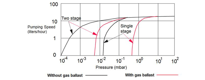
Figure 11| Effect of gas ballast on pumping speed3 (Figure courtesy of Nigel S. Harris M. Sc, C. Phys., author “Modern Vacuum Practice“, 3rd Revised Edition, Kurt J. Lesker Company, 2007)
Cold Traps
In addition to gas ballast, another approach to pumping gases containing condensed vapors or moisture is to remove them prior to entering the pump. This is done via a cold trap (aka inlet condenser) located at the pump inlet.
A condenser (Fig. 12) works by cooling the pumped gas below the condensation temperature of the vapors (moisture and others) carried in the gas. The vapors turn into a liquid and collect on the interior surfaces of the heat exchanger inside the condenser, preventing them from entering the pump. The resulting condensate is collected and removed. Inlet condensers can be water cooled using a shell and tube heat exchanger or cooled with refrigerant or cryogens such as liquid nitrogen.
The condenser also helps minimize the backstreaming of oil vapors from the pump into the vacuum chamber. Even with an inlet condenser, a rotary pump can still accumulate condensed contaminants in the oil. Therefore, often both an inlet condenser and a gas ballast are used, for maximum vapor handling capability with minimum sacrifice of pumping capacity.
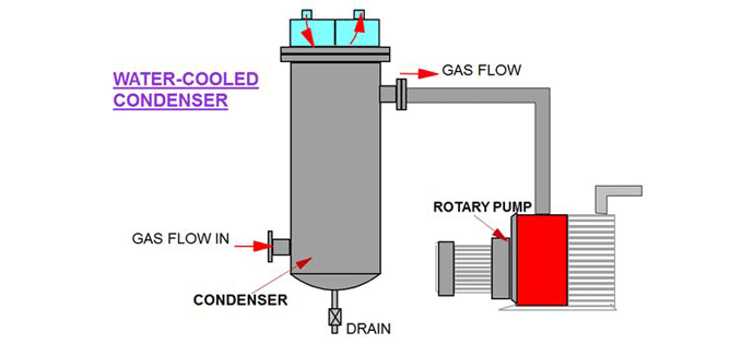
Figure 12 | Condenser located at the pump inlet (courtesy of Edwards Vacuum)
Foreline Traps
In any vacuum system with a pressure lower than 0.75 Torr (10-1 mbar) there is a potential for backstreaming, which is the migration of oil vapors against the flow of pumped gas, and back into the vacuum furnace chamber (Fig. 13). Backstreaming (c.f. Oil Sealed Rotary Vane Pumps Part 1) is a result of vaporization of the oil under low pressure. It causes contamination, as the oil deposits as a film on interior furnace surfaces and can interfere with the process being performed.
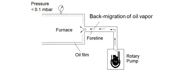
Figure 13 | Back migration of oil vapors from the rotary vane pump3 (Figure courtesy of Nigel S. Harris M. Sc, C. Phys., author “Modern Vacuum Practice“, 3rd Revised Edition, Kurt J. Lesker Company, 2007)
One way to prevent backstreaming is the use of a foreline trap (Fig. 14), which is a molecular sieve installed on the inlet of the pump. It is filled with activated alumina (also referred to as sorbent), which traps and collects the oil vapors. The alumina media is replaceable and must be changed at the same interval as the pump oil, typically every 6 months although this depends on usage frequency. The foreline trap will stop 99% of the oil vapors.
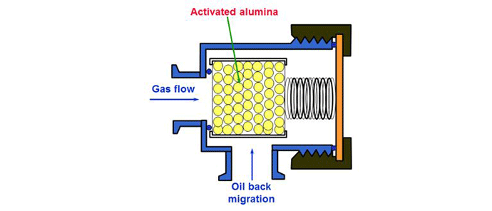
Figure 14 | Foreline trap (courtesy of Edwards Vacuum)
The alumina also will remove moisture from the foreline and collect it as liquid water. Over time, this will slow pump-down as the alumina becomes clogged with water. For this reason, when moisture is present in the pumped gas it is recommended that an inlet condenser be used with the foreline trap.
When a foreline trap is used, it is necessary to bypass the trap (Fig. 15) during roughing, which is the period of high flow initial pump-down at higher pressures. Only after roughing is complete and higher vacuum is achieved is backstreaming a concern. At this time the gas is then routed through the foreline trap. This bypass arrangement prevents the alumina from quickly and unnecessarily becoming clogged during the high flow of gas and vapors pumped during roughing.

Figure 15 | Foreline trap bypass arrangement (courtesy of Edwards Vacuum)
Although foreline traps are common, the first defense against backstreaming is to use a pump oil with a low vapor pressure, which is less prone to vaporization and therefore less likely to backstream.
In addition to the foreline trap, other accessories are used on the pump inlet side to capture moisture, vapors and solid contaminants. Among these are the desiccant trap, zeolite trap, catalytic trap, catch pot, and dust trap. The selection of trap(s) is based on the specific application and the constituents of the pumped gas.
Summary
More could and perhaps should be said on the subject of oil sealed rotary vane pumps but the key is to recognize their importance to the overall performance of your vacuum process. Know how they operate and how to use them properly. Change the pump oil every month (300 hours) and perform the other steps necessary to take care of them and you will be rewarded with years of trouble-free pump operation.
Also, see our blog on the Different Types of Vacuum Pumps Here
References
- Herring, Daniel H., Vacuum Heat Treatment, Volume I, BNP Media, 2012.
- Mr. David Sobiegray, Edwards Vacuum, technical contributions, and private correspondence.
- Figures courtesy of Nigel S. Harris M. Sc, C. Phys., author “Modern Vacuum Practice“, 3rd Revised Edition, Kurt J. Lesker Company. 2007, ISBN 09555150116 (available on VLPC and Amazon)


Hi, Natalie from Social Buzzzy here. I've found a breakthrough for Instagram engagement and just had to share it with you!
Social Growth Engine introduces an extraordinary tool that skyrockets Instagram engagement. It's simple:
- Focus on creating incredible content.
- Economical at less than $36/month.
- Safe, efficient, and compliant with Instagram.
I've seen fantastic results, and I know you will too! Boost your Instagram game now: http://get.socialbuzzzy.com/instagram_booster
Cheers your success,
Natalie